Sometimes it may be useful to set figures or segments into a specific pose that would be difficult to do only by dragging with the mouse. This may include angles that are not up, down, left or right and so cannot be set using the alignment feature with the arrow keys.

The solution is to position figures to specific values by clicking '
Input Segment Values' or '
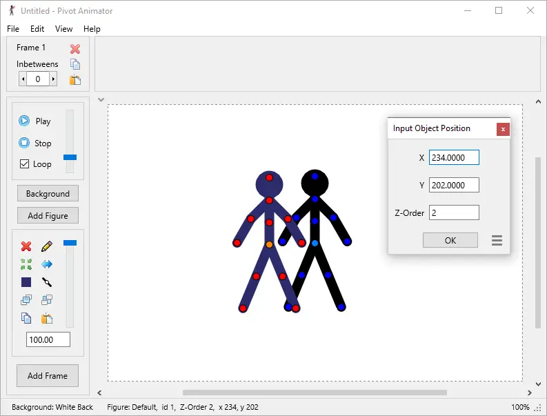
Input Object Position' in the Edit menu or by using the 'I' keyboard shortcut. In the figure builder this will edit the selected segment. In the main window this will edit the segment for the red handle under the cursor or the figure position for the orange handle under the cursor. If there is no handle under the cursor then it will edit for the last handle clicked or the selected figures. The angle, bend angle and length, or figure x and y position and z-order, can then be modified and the figure will update as the changes are made. The segment thickness and segment or polygon z-order are also shown if editing in the figure builder. Values can be typed in or increased or decreased by dragging vertically in the boxes or using the mouse wheel over the box. Hold the Shift key to make finer adjustments using the mouse wheel or dragging. The Tab key can be used to step through the values. Note that segment length cannot be set to 0 since this may make it impossible to select the segment again. Click the OK button to apply the changes and close the window or click the cross in the top right corner or press Esc to close the window and undo any changes that were made. The same trick can be used to position the
virtual camera.
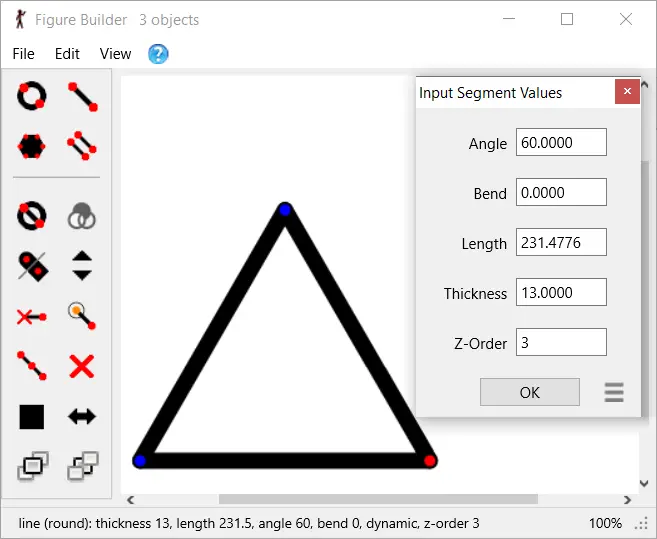
Select 'Input Segment Values' from the Edit menu or press the 'I' key to manually enter values for a segment.
This makes it easy to create perfect shapes such as this equilateral triangle.
Hover the cursor over the orange origin handle of a figure and press 'I' to manually edit the figure's position values
Hover the cursor over a camera handle and press 'I' to manually edit the camera pose values

All values in the window can be
copied and pasted with a single operation by clicking the menu button in the bottom right corner of the window or right clicking a blank area of the window. The shortcuts
C and
V can also be used. This saves having to copy and paste each value one at a time. The values are stored as text in the Windows clipboard, separated by colon characters.
 Input of segment values can be combined with the edit mode option to
 move only the point at the end of the segment being modified. Hold R while pressing the I key or select the option in the canvas toolbar.

Input of segment values can be combined with the
isolated rotation option to avoid rotating attached dynamic segments. Hold Caps Lock while pressing the I key or select the option in the canvas toolbar.

Changes to segment thickness and z-order in the figure builder can be applied to a branch by holding Shift while pressing the I key and then changing the value. For thickness, all segments in the branch will be set to the same value. For z-order, all segments and polygons will be shifted by the same amount to keep their relative order.
Apply to Multiple Frames
Changes to the figure position or camera position values can be applied to multiple frames when multiple frames are
selected. Note that only the values changed will be applied to the frames by default, which allows you, for example, to set the same X position for a figure in selected frames, but leave the Y position and other values unchanged. However, checkboxes are shown to allow you to also set unchanged values if you wish.
Note that setting the segment values cannot currently be applied to multiple frames.
Segment Angle (Relative vs Absolute)
Note that by default the Angle ranges from -180° to 180°. 180° corresponds to a segment pointing to the left and 0° is directly to the right. These angles are absolute, meaning that they're all measured from the canvas axes, however you can switch to
relative segment angles by selecting the option in the popup menu, or using the
Ctrl+R shortcut, so that the angle is relative to the segment it attaches to (it will make no difference for segments attached to the orange origin joint, unless the figure is
joined to another). The absolute angle is the angle of the segment it attaches to plus the relative angle. You will then see that the word 'Angle' changes to 'Angle (Rel)'. This can be useful in certain cases. For example, if you'd like to create a chain of segments forming an arc then you can set the values for the first segment and then copy and paste them for the others without having to manually compute the absolute angle of each. To make a segment be in line with the segment below, simply set its relative angle to 0.